- Written by ZILA GmbH
- font size decrease font size increase font size
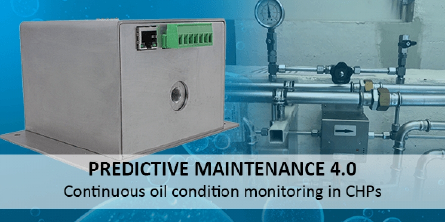
Predictive Maintenance 4.0 - Continuous oil condition monitoring on the example of two CHPs
In this article we will demonstrate on the basis of two system models how you can prevent plant inefficiency and make use of enormous savings using our oil condition sensor FluidIX Lub-6.
Inline oil condition analysis as a new sales market

Inline oil condition monitoring entered the market as a completely new technology just a few years ago, and, since then, has continued to evolve due to the increasing digitalisation, the implementation of more advanced processes and maintenance strategies, as well as Industry 4.0.
Today, there are already quite a few oil condition sensors available. However, they cannot always be directly compared with each other due to differences in the measuring methods used. With some measuring methods, such as oil chemistry measurement, it is possible to detect at whether a chemical compound is possibly decomposing at a very early stage. Other methods, in contrast, such as particle counting or vibrations, do not consider this factor.
Moreover, it should be noted that currently there is no in-line sensor on the market capable of differentiating between different wear metals. This task is currently done by special oil analysis laboratories. For this purpose, samples are taken from the respective machines, sent to such labs and then analysed by experts.
Oil condition monitoring: Technologies and measuring methods in comparison
Currently, there are only a few sensor technologies that function just as reliably and precisely as laboratory methods.
In order to get a better understanding of the reasons for this, let us first look at the standard laboratory procedure for evaluating the oil chemistry.
The FTIR spectroscopy
For the FTIR spectroscopy oil samples are measured and analysed with the help of a so-called spectrometer. First, the samples are illuminated, then the infrared spectrum is detected and, subsequently, the spectral bands are determined, which ultimately show the condition of the oil examined. In the end, those and other parameters (e.g. oxidation, nitration, water content, etc.) are compiled in a report in order to obtain information about the current oil condition of a machine or plant, and, based on that, to derive appropriate measures for service planning and maintenance.
Advantages and disadvantages of the FTIR spectroscopy
| Advantages | Disadvantages |
| Precise measuring method | Plant operators always have to rely on a lab to determine the current oil condition of the machines |
| Provides exact information about many parameters relevant to the oil condition |
Higher costs and more effort than necessary, because:
|
The NDIR technology

The oil sensor FluidIX Lub-6 from ZILA GmbH, in contrast, works on the basis of the optical NDIR technology (non-dispersive infrared technology). This measuring method does not analyse the entire infrared spectrum, but only the spectral bands reflecting the aging process of the oil. This works by specifying wavelength filters in advance. As soon as oil is pumped through the sensor, it contacts the measuring cuvette and is illuminated by an IR radiator. Since the molecules, due to their typical bonding forms in the oil, absorb infrared light differently at certain wavenumbers, part of the light is not transmitted any further. The other part of the transmitted light then hits the wavelength filters, which only allow a narrow-band range to pass through unhindered. In the end, this range is captured by the IR detector and thus, the intensity of each band can be measured.
Advantages and disadvantages of the NDIR technology
| Advantages | Disadvantages |
| Oil condition assessment even before wear metals occur | No wear metal detection possible |
| Enables quick reaction of plant operators and early introduction of measures to prevent machine damage | |
| Miniaturised and compact measuring method (only those parts of the IR spectrum with aging effect are recorded) | |
| In-line application for continuous oil condition monitoring | |
| Significantly lower costs for plant operators |
We have combined all these advantages of the NDIR technology in an in-line sensor for oil condition monitoring, and would now like to give you a few more details to this sensor.
In-line oil condition sensor FluidIX-Lub-6
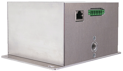
Our in-line oil sensor FluidIX Lub-6 for permanent oil condition monitoring has the decisive advantage of direct integration into existing machine and plant concepts.

This is due to the innovative NDIR technology used, which provides real-time information on parameters such as oxidation, nitration, water content, additive content (phenols), sufation and glycol. Moreover, it is possible to record six measuring channels and two reference channels at the same time by means of 8 different wavelength filters. In this way, conclusions about the current condition of the oil in a machine can be drawn, based on a signal shift occurring in the course of the operating time.
Comfortable integration of the sensor into existing plants
The sensor system has the following process connections:
- Ethernet port for quick and easy commissioning and configuration via web interface
- Digital signals and Modbus TCP for direct connection to a control system
- GSM modem for direct connection to a cloud (optional)

Example 1: 800 kWel natural gas CHP for district heating supply
Supply concept

In our first practical example, oil change planning is based on the number of operating hours, supported by individual external lab analyses. The engine oil circuit here consists of the engine itself, which interacts with an oil pan of 140 litres capacity and a 1,000-litre oil tank.
As soon as the oil lab suggests the remaining number of operating hours, the oil is drained from the engine to the tank after this period of time. Then, the used, aged oil is exchanged with that of a second tank so that fresh oil can enter the engine again.
Integration of the sensor in the CHP
For the purpose of district heating, the oil coming from the engine is led into the tank, passing through the FluidIX Lub-6, with the help of a constantly running oil feed pump.
Therefore, the sensor was installed in the return line between the tank and the engine of the CHP. The plant operator equipped this return line from the engine with a T-piece; at the outlet he installed a stopcock, the oil sensor itself, the pump and another stopcock in series. Additionally, a valve bar on the suction side was connected to the outlet line.
In-line oil condition sensor in operation
During the external laboratory analyses, it turned out that all values, except for oxidation, hardly showed any abnormalities and thus only this is an indication for an oil change. The following diagram illustrates the measurements of the oxidation curve recorded by the oil sensor.

The sensor was installed after 328 operating hours. The first oil change was carried out after 1,988 operating hours, followed by another oil change after another 1,960 operating hours. After each oil change, the oxidation value is constantly low, but rises as time of operation in the CHP goes by. Moreover, maintenance measures were undertaken in the CHP for a short period of time (at operating hour 2,600), which is why the plant was temporarily at a standstill and the oxidation remained almost unchanged. The results of the external laboratory analyses are marked with an asterisk (*) on the graph. No data recording was possible in the range of 4,000 operating hours because the FluidIX Lub-6 was disassembled at that time.
Example 2: 2000 kWel natural gas CHP for replenishing engine shortfalls
Supply concept

In our second application example, based on practical experience, the entire process was also accompanied by an external oil analysis laboratory. In this case, the engine oil circuit consists of the engine itself and a 250-litre engine oil sump, interacting with a 300-litre oil tank. Besides, an engine sprayer and a return line to the sump are also part of the circuit.
Shortages are compensated for by a pump from a fresh oil tank to a deep tank. This means that when the oil has exceeded the wear limit determined by the laboratory, it is manually pumped into the waste oil tank from the engine oil sump and the deep tank. The waste oil may then be removed by a specialised disposal company and the plant can be refilled with new oil via a fresh oil tank. Both the refilling process and the removal of the waste oil to be disposed of, are done by means of a tanker truck.
Integration of the sensor in the CHP
The sensor system was installed in the line between the engine, the engine oil sump and the oil deep tank.
The core of this application is the pump interacting with the oil sensor.
In order to ensure that the oil circuit runs smoothly, the pump was installed in series with the oil sensor along with a T-piece on the oil line to the engine. Another T-piece was connected to the oil spray line of the engine so that the oil could drain from the machine into the deep tank.
Via its digital output, the FluidIX Lub-6 regulates the connected pump completely automatically and switches it on and off by itself. This means that the pump is activated when the sensor switches on from standby mode. Measurements start and oil is continuously pumped through the oil sensor for about 4 minutes. Once this is done, the device goes back to standby mode and the pump switches off again.
In-line oil sensor in operation
As the following graph indicates, the evaluation of the external laboratory analyses also showed that, apart from oxidation, all the other parameters were found to be normal and, once again, only oxidation is an indicator of an approaching oil change.

In this application, the sensor was installed in the CHP at a slightly later point in time (at approx. 1,440 operating hours). The first oil change was carried out after 2,500 operating hours, a second one followed after 4,470 operating hours. This shows again that the oxidation value is still low after an oil change, but rises with increasing operating time in the CHP. The results of the external laboratory analyses are also marked with an asterisk (*) in the graph above.
The oxidation curve can be measured excellently using our oil condition sensor FluidIX Lub-6. In this application example, we can see that the pump operation of 4 minutes per 2 hours feeds a significantly too low amount of oil through the sensor, but this can easily be fixed by changing the time interval for pump operation.
Summary
All in all, we can say that oil aging processes can be monitored and observed very precisely based on the oxidation with our oil condition sensor FluidIX Lub-6. Thanks to its innovative technology, the sensor allows for permanent in-line monitoring of the oil condition and is therefore an attractive product for each and every plant operator.
In the near future, the range of functions of our oil condition sensor FluidIX Lub-6 will be upgraded even further:
- Acoustic alarm signal at the digital output as soon as a critical condition is reached and the set limit value has been exceeded.
In this way, the plant operator can quickly take an oil sample and send it to a laboratory to have the current oil condition checked. - Development of a measuring method for on-line detection of wear metals
More product impressions
Should you require more information about this product, please visit the product page of our oil sensor FluidIX Lub-6 or contact our sales team directly via the contact options listed below!
Prices and availability
Do you have any questions or require specific consultation for your application? We will be pleased to prepare an individual, non-binding offer and advise you on your application.
Please do not hesitate to contact us now, using the following contact options:
Phone: +49 (0) 3681 86-7300
Email: This email address is being protected from spambots. You need JavaScript enabled to view it.
Contact form.
Our experienced sales team is looking forward to your enquiry!